Since the thermal conductivity of solid materials is inversely proportional to the temperature change of the electrical system, this requires the thermally conductive material to exhibit temperature-adaptive heat transfer capabilities and be integrated into the thermal management of the electrical system under dynamic load conditions. Managing heat in electrical conductors is a major challenge in meeting sustainable energy use and power reliability needs, especially in power electronics and energy-critical motors. To achieve these different functions, such as thermal reliability and electrical reliability, the structure of the thermally conductive material needs to be properly designed.
02. A snapshot of the results
Recently, cloth method The research team of Shenqiang Ren of Luo University proposed a layered thermally conductive nanocomposite fabric, which is composed of a nanostructured ceramic conformal coating and a mixed arrangement of ultra-high molecular weight polyethylene fibers, which can customize the heat dissipation of electrical conductors. The mixed arrangement of thermal interface has very ideal The anisotropic high thermal conductivity of up to 0.98W/mK and the dielectric strength of 3.4. In addition, the electrically insulated interface exhibits high performance and reliable electrical systems under dynamic load conditions. Under the same electrical load, non- The surface temperature of uniform ceramic-polymer encapsulated conductors is 17.8°C lower than that of polymer-encapsulated conductors. The research results were published in “Applied Materials Today” under the title “Hierarchical thermal-conductive polymer nanocomposites for thermal management”.
03. Graphic introduction
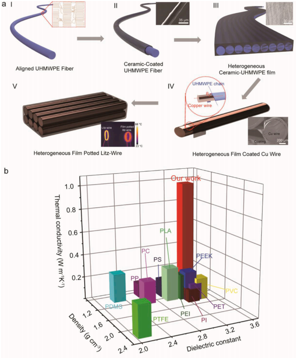
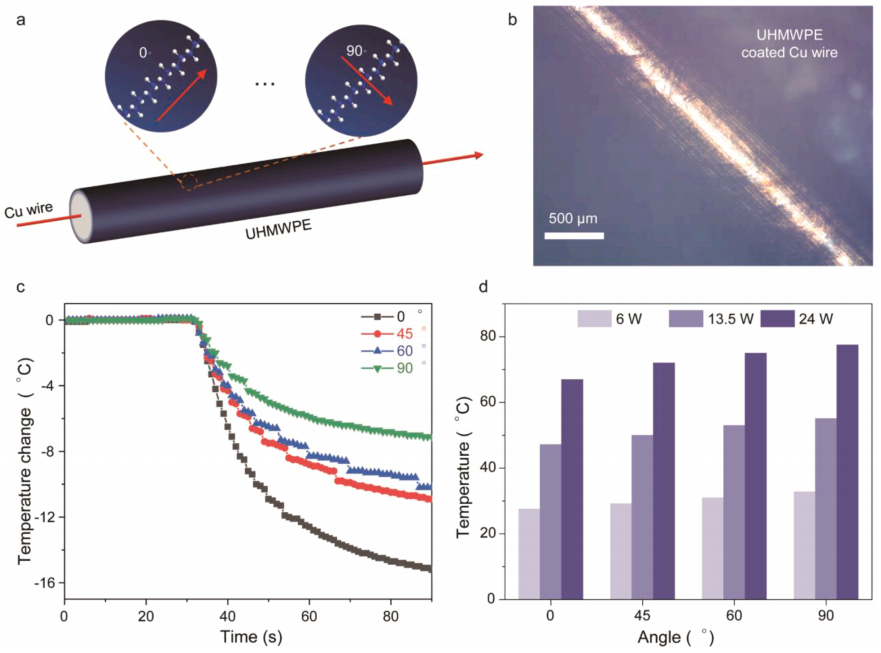
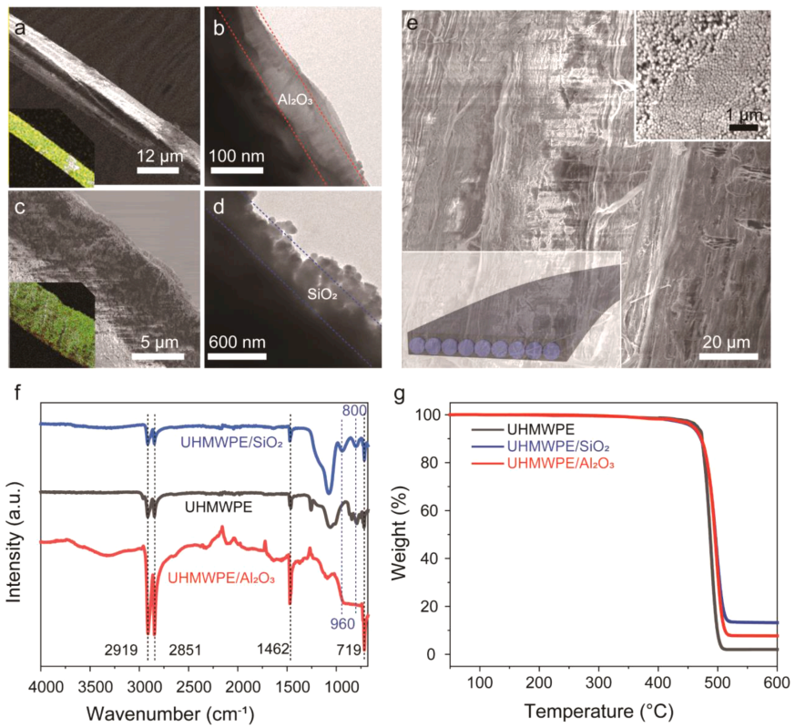
Figure 3 a. Scan of ultra-thin alumina-coated UHMWPE fiber Electron microscopy and its corresponding energy dispersive x-ray spectroscopy (EDS). b. Transmission electron microscope (TEM) image of ultrathin alumina-coated UHMWPE fiber. c. Scanning electron microscopy of silica-coated UHMWPE fiber and its corresponding energy-dispersive x-ray spectroscopy (EDS). d. Transmission electron microscope (TEM) image of silica-coated UHMWPE fiber. e.UHMWPE/silica heterogeneous film. The inset shows the assembly of silica nanoparticles coated on UHMWPE fibers. f-g. Fourier transform infrared spectroscopy (FTIR) and thermogravimetric analysis of UHMWPE, UHMWPE/alumina and UHMWPE/silica.

The relationship between the temperature attenuation of the �� line and the current direction and UHMWPE chain direction. (d) Temperature diagram of UHMWPE-coated copper wire under different input powers.

Figure 3 a. Scan of ultra-thin alumina-coated UHMWPE fiber Electron microscopy and its corresponding energy dispersive x-ray spectroscopy (EDS). b. Transmission electron microscope (TEM) image of ultrathin alumina-coated UHMWPE fiber. c. Scanning electron microscopy of silica-coated UHMWPE fiber and its corresponding energy-dispersive x-ray spectroscopy (EDS). d. Transmission electron microscope (TEM) image of silica-coated UHMWPE fiber. e.UHMWPE/silica heterogeneous film. The inset shows the assembly of silica nanoparticles coated on UHMWPE fibers. f-g. Fourier transform infrared spectroscopy (FTIR) and thermogravimetric analysis of UHMWPE, UHMWPE/alumina and UHMWPE/silica.


