3D composite fabricForming roller mold design
Abstract 3D composite fabric is A new type of absorbent composite fabric. Its forming equipment is a composite concave-convex embossed roller mold that integrates forming, shaping, adsorption and transmission, and various transmissions. The difficulty in design is to adapt to various raw material thicknesses and peeling forces. requirements and the height of 3D forming, and also need to adapt to the requirements of high-speed production above 300 m/min. By analyzing the forming process and setting process of the fabric, the overall design of the composite mold was carried out, and the forming structure, setting structure and transmission structure were introduced. . This mold solves various difficulties and achieves good results through ingenious structural design and simulation technology.
Keywords 3D composite fabric; absorbent body; roller mold; forming; shaping
0 Introduction
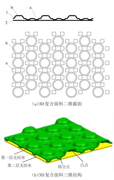
3D composite fabric is a new type of absorbent composite fabric developed in recent years and is widely used in maternal and child hygiene products and other industries. Figure 1 shows a skin-contact three-dimensional composite fabric for absorbent articles. The 3D composite fabric is made of two layers of hydrophilic hot air non-woven fabrics bonded by local hot melt. The first layer of non-woven fabric 1 and the The hydrophilicity of the two layers of non-woven fabric 2 increases in sequence. As shown in Figure 1(a), convex points b are arranged in the part other than the fusion point a of the first layer of non-woven fabric. The convex points b and the fusion point a are arranged alternately. [1], forming a 3D composite fabric as shown in Figure 1(b). The key and difficulty in realizing the production of 3D composite fabrics on high-speed production lines is the design and manufacturing of roll forming molds [2]. Online production of 3D composite fabrics has better forming effects, aesthetics and peeling force than offline production [3 ], also reduces production costs. The difficulty lies in how to achieve the formation and shaping of hydrophilic hot-air non-woven fabric bumps during high-speed production, and to achieve the requirement of no delamination during use. The following introduces the structural design of an online roll forming mold for 3D composite fabrics that can solve these difficulties and meet market requirements.
3D composite fabric products
1. The first layer of non-woven fabric 2. The second layer of non-woven fabric; a . Fusion point b. Bump
1 Process Analysis
1.1 Forming process analysis
The first layer of fabric must achieve the bump forming effect shown in Figure 1 , must have a certain thickness and ductility, otherwise it will easily break. Practice has proven that the quality of the first layer of hot-air non-woven fabric is generally not less than 23 g/m2, and the drawing depth is generally not more than 1.5 mm. The quality of the second layer of non-woven fabric is preferably above 18 g/m2 [4]. During the forming process, material rebound, thickness and different depth requirements of customers should be fully considered, so the forming structure must consider a structure with adjustable drawing depth.
The forming punch and the concave mold rotate in opposite directions. During the rotation process of inserting the convex teeth of the convex mold into the corresponding position of the concave mold, they cannot contact and interfere with each other, otherwise the convex teeth It may break, so the meshing process of the convex and concave molds must be simulated during design, and the meshing process at the maximum meshing depth must be simulated to ensure that the parts will not interfere.
1.2 Analysis of shaping process
Since the raw material is 0.06~0.08 mm thick hot air non-woven Cloth is thin and soft. If it cannot be bonded with glue, it is difficult to shape it after forming. The shaping structure is very important. In addition to reducing reverse osmosis, the second layer of non-woven fabric shown in Figure 1 also has two functions through the melting points around the bumps: ① Fusion of the two layers of non-woven fabric into one; ② Shaping the bumps. When designing the shape, it is also necessary to consider that the bumps cannot deform during the transfer process from the forming position to the shaping position, so the shaping structure needs to consider two aspects: melting and transfer shaping.
1.3 Requirements for relative phase fixation of concave roller and convex roller
Users will encounter If the raw materials are replaced as needed or the material breaks during the production process, the convex and concave molds must be separated and re-threaded. The design of the mold structure must ensure that the relative phase of the convex and concave molds remains unchanged, otherwise the mold will be recombined again. Causes damage to the convex and concave molds.
1.4 Transmission structure analysis
Combined with the above analysis, the mold needs to be formed and finalized at the same time It has functions such as conveying and conveying, and is more complex than a general roller mold. The diameter of each mold roller is inconsistent, so the design of the transmission structure must ensure that the linear speed of the same layer of material is consistent, otherwise wrinkles or delamination and other poor fit will occur. Phenomenon.
2 Structural design
2.1 Forming structure design
Figure 2 shows the structure of the mold forming part. The male mold component 2 is placed above the mold base, and the female mold component 1 is placed below the mold base, using a frame type mold base 3[5] , the pressurizing mechanism 4 (cylinder pressurization) is placed above the mold base, the adsorption transfer mechanism 5 is arranged on the front and rear sides of the die, and the air suction port is externally connected to an air pump or Roots pump of suitable power.The diameter of the wheel ensures that the linear speed of the die and anvil roller is consistent. The transmission connection of the four mold rollers and the phase control of the convex and concave molds are shown in Figure 8. The concave mold is fixed in the middle position and is directly driven by the fixed flange. The convex mold eccentric coupling 9 is connected for transmission, 2 The anvil roller is connected and driven through the inner ball cage coupling 12; the male and female molds realize the functions of range positioning and precise positioning respectively through two pairs of transmission gears 8 and 10. The gear 8 can be disengaged as the male and female molds are disengaged. , another pair of gears 10 in the middle of the transmission mold base still maintain meshing when the male and female molds are disengaged. This requirement is achieved through the eccentric coupling of the male mold to ensure that the relative position between the male teeth and the female mold is ensured when the male and female molds are disengaged. It is crucial that the phase does not change.
Diagram of transmission between die and anvil roller
1. Anvil roller pulley 2 . Die pulley 3. Anvil roller pulley 4. Idler pulley 5. Idler pulley 6. Timing belt
Connection transmission diagram
1. Concave mold assembly 2. Punch mold assembly 3. Mold frame 4. Pressure mechanism 7. Anvil roller assembly 8. Convex and concave mold precise positioning transmission gear 9. Punch mold eccentricity Coupling 10. Positioning transmission gear of male and female molds 11. Pulley between female mold and anvil roller 12. Ball cage coupling inside anvil roller 13. Female mold coupling
The power transmission path is: the motor transmits the power to the concave mold assembly 1 through the synchronous belt, the concave mold assembly 1 transmits the power to the male mold assembly 2 through the gear, and the concave mold assembly transmits the power to the male mold assembly 2 through the synchronous belt transmission system. The power is transmitted to the two anvil roller assemblies 7. The transmission ratio of these gears and synchronization wheels is consistent with the corresponding mold roller diameter ratio requirements to ensure that the linear speed of each roller surface is consistent.
2.5 Overall structure of the mold
3D composite fabric forming roller mold is shown in Figure 9 , the female mold assembly 1 is fixed in the middle of the mold frame, the remaining three mold rollers surround the circumference of the female mold, the male mold assembly 2 is on the right side of the female mold assembly, and the two anvil rollers are on the upper and lower sides respectively. The mold assembly can move up and down along the slide. The punch is fixed on the inclined block 6 through the pressure of the cylinder pressurizing mechanism 4. The depth of the male teeth of the punch inserted into the female mold can be adjusted at will through the inclined block to obtain the best result. Best forming effect. The anvil roller assembly 7 can slide on the slide, and is pressurized by the cylinder pressure mechanism 4 to tightly press the anvil roller assembly 7 on the surface of the concave mold. In the heated state, it interacts with the convex points on the surface of the concave mold to make the two layers of non-woven fabric The cloth is melted and bonded, while ensuring that the formed bulge does not deform.
Overall structure of the mold
1. Female mold component 2. Punch mold Components 3. Mold base 4. Pressure mechanism 6. Incline block 7. Anvil roller assembly
3 Mold working principle and process
The working principle of the mold is shown in Figure 10. The punch 2 and the concave mold 1 rotate toward each other, and the convex teeth of the punch 2 drive the first layer of non-woven fabric 3 to mesh with the corresponding phase of the concave mold 1. A bulge is formed in the hole. During the rotation to the first anvil roller 6, the formed bulge is always firmly adsorbed in the die through the negative pressure area A and undergoes plastic deformation under the action of heat. The second layer of non-woven fabric 4 enters between the first anvil roller 6 and the concave mold 1, and the two layers of non-woven fabric are melted and bonded through pressure and heat, and then pressed again by the second anvil roller 7 to further strengthen the two layers. The degree of bonding of non-woven fabrics, and finally the composite 3D composite fabric 5 is output.
Mold working principle
1. Concave mold 2. Punch mold 3. First layer of non-woven fabric 4. Second layer of non-woven fabric 5. 3D composite fabric 6. First anvil roller 7. Second anvil roller A. Negative pressure area
4 Conclusion
3D composite fabric forming roller mold is a composite mold that integrates shaping, shaping, material compounding, adsorption transfer and complex transmission structure. Only suitable for flexible materials with microelastic and thermoplastic properties and raw material thickness not exceeding 0.2 mm. The design scheme can be used for production on high-speed production lines or for offline production of 3D composite fabrics, and can be widely used in industries such as diapers, pull-ups and sanitary napkins. After a large amount of practice verification, the mold can fully meet the online and offline production of line speeds above 300 m/min, with good results.

